| ISRO Astrosat page | Click to download Astrosat Handbook |
| SPIE 2014 paper on Astrosat | Astrosat Outreach Booklet |
ASTROSAT is a multi-wavelength astronomy mission on an IRS-class satellite in a 650-km, near-equatorial orbit. It was launched by the Indian launch vehicle PSLV from Satish Dhawan Space Centre, Sriharikota on September 28, 2015. The expected operating life time of the satellite will be more than five years.
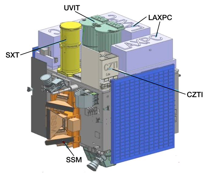
On board ASTROSAT are five astronomy payloads for simultaneous multi-band observations:
- Twin 38-cm Ultraviolet Imaging Telescopes (UVIT) covering Far-UV to optical bands.
- Three units of Large Area Xenon Proportional Counters (LAXPC) covering medium energy X-rays from 3 to 80 keV with an effective area of 8000 sq.cm. at 10 keV.
- A Soft X-ray Telescope (SXT) with conical foil mirrors and X-ray CCD detector, covering the energy range 0.3-8 keV. The effective area will be about 120 sq.cm. at 1 keV.
- A Cadmium-Zinc-Telluride coded-mask imager (CZTI), covering hard X-rays from 10 to 150 keV, with about 6 deg field of view and 480 sq.cm. effective area.
- A Scanning Sky Monitor (SSM) consisting of three one-dimensional position-sensitive proportional counters with coded masks. The assembly is placed on a rotating platform to scan the available sky once every six hours in order to locate transient X-ray sources.
ASTROSAT will operate as a proposal-driven general purpose observatory, with main scientific focus on:
- Simultaneous multi-wavelength monitoring of intensity variations in a broad range of cosmic sources.
- Monitoring the X-ray sky for new transients.
- Sky surveys in the hard X-ray and UV bands.
- Broadband spectroscopic studies of X-ray binaries, AGN, SNRs, clusters of galaxies and stellar coronae.
- Studies of periodic and non-periodic variability of X-ray sources.
Open observing time on ASTROSAT will start one year after launch, for which proposals will be invited from the astronomy community. The primary data archive for ASTROSAT will be located at the Indian Space Science Data Centre (ISSDC) near Bangalore, India.
The Ground Command and Control Centre for ASTROSAT is located at ISTRAC, Bangalore, India. Commanding and data download will be possible during every visible pass over Bangalore. Ten out of 14 orbits per day are visible to the ground station for long enough to accomplish full data download.
To propose for ASTROSAT observations and to use ASTROSAT data please visit the AstroSat Science Support Cell