Coded Aperture imaging aims to find the location of a source in the field of view by finding the shift, from central position, of the mask shadow cast by it on the detector[1]. In practice there would be multiple sources in the field of view at any given time, so to avoid ambiguous results, it is desirable that the autocorrelation of the mask pattern has only a single peak at zero shift. It is possible to obtain this if the mask pattern is chosen to be an Uniformly Redundant Array (URA), and it is ensured that every detector element is exposed to one full mask pattern, possibly in cyclic permutation[4].
 
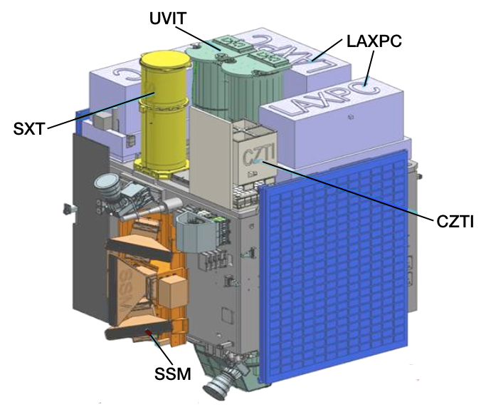
The design of the two coded mask instruments on ASTROSAT Scanning Sky Monitor (SSM) cameras and the Cadmium Zinc Telluride Imager (CZTI) are such that the size of the mask plate in the direction of coding is the same as that of the detector itself. In such a design (called a 'box-type' or 'simple' system) exposure to the full mask pattern is not possible anywhere except exactly at the middle of the coded field of view. At all other angles only a part of the shadow of the mask falls on the detector, the rest being obscured by the camera walls. This prevents the URA-property of a single peak in the response function from being realised. In the otherwise flat sidelobe pattern, undulations now appear. However, of all possible patterns with the same transmission, URAs still figure among those that yield minimum sidelobe levels in the response function, and therefore remain the patterns of choice.
 
URAs are constructed out of cyclic difference sets (CDS): these are sets of integers characterized by three numbers n, k and z. A CDS D is a collection of k integers {I1, I2, .... , Ik} in the range 0 ≤ Ii < n, such that the congruence Ii – Ij = J (mod n) has exactly z solution pairs (Ii, Ij) within D[2]. A CDS can be represented as a binary sequence ai, 0 ≤ i < n, in which an element ai is set to 1 if i is a member of the CDS, and set to zero otherwise. In the mask pattern the 1-s of the CDS binary sequence would represent open holes, and the 0-s the closed holes. This would be called an URA pattern. Clearly, the ratio k/n would decide the transmission fraction of the URA mask.
 
URAs can be constructed for various levels of transmission, up to a maximum of about 50%. Usually a smaller transmission fraction is also associated with a better image definition. An extreme example would be a pin-hole camera where an excellent image definition is obtained by reducing the transmission almost to zero. Given that the SSM and the CZTI detector modules have relatively small area and that the exposure time in any given direction would be limited, the priority in the present case was given to obtaining as much transmission through the mask as possible so as to maximise photon counts in an exposure. With this in view, it was decided to obtain the pattern using pseudo-Noise Hadamard sets which yield near-50% transparency[3],[5].
 
A pseudo-noise Hadamard set is constructed from a shift-register algorithm[6]: Let 
 
 
represent a polynomial of degree m in x. From these one chooses "primitive" polynomials, for which the coefficients pj can take values only 0 or 1. In order to keep the order intact, pm must then always be 1. Among these primitive polynomials, one then picks "irreducible" ones, i.e. those which cannot be factorised. Such an irreducible primitive polynomial of degree m can then be used as a generating function of a mask pattern of length n = 2m – 1. Let this be represented by a sequence 
 
 
where ai are either 0 or 1, with 1-s representing open mask elements. One can choose the first m elements, 
 
 
arbitrarily. The following elements are then generated using the shift register algorithm 
 
 
This is the method that has been used in the generation of the CZTI and the SSM masks.
 
Coded Masks for the SSM
 
The SSM detector wires are of 60 mm length, with a nominal resolution of 1 mm. This yields nearly 60 independent detector elements along the wire. An optimal mask design would have mask element widths matching the detector resolution. The closest, in this case, would be a 63-element mask ( m = 6), with basic element width of 0.95 mm.
 
With this in view, sixth order primitive polynomials were chosen as generating functions for the mask pattern. Irreducibility of these polynomials were checked using the Maple software. The polynomials were then used to generate mask patterns using the shift register algorithm, and the patterns thus produced were subjected to cyclic autocorrelation to check sidelobe patterns. Six of these patterns were found to have perfectly flat sidelobes in cyclic autocorrelation, which were then chosen for implementation as URAs. It was decided that all six mask patterns will be fabricated and placed side-by-side in the cross-coding direction, so that a limited source location can be obtained within the ~ 100° field of view across the coding direction.
 
The six generating functions used for the URAs are


The first 6 mask elements can be chosen arbitrarily in each case, different choices amounting to different cyclic permutations of the final mask pattern. In order to avoid continuous open slits at the starting edge, which might mechanically weaken the mask plate structure, the following starting sequences (row-wise) were chosen for the six generating functions above:
 
1   1   0   1   0   1 
0   0   1   0   1   0 
0   1   0   0   0   1 
1   0   0   1   0   0 
0   0   1   0   1   1 
1   1   0   1   0   1 
 
Click here to view the resulting six mask patterns of the SSM.
 
The autocorrelation functions of the six URA mask patterns chosen for the Scanning Sky Monitor are displayed in the figures below. Successive patterns are shifted vertically for clarity. The figure on the left shows cyclic autocorrelation and that on the right the shadowed autocorrelation relevant for a box-type camera. Click on the images to view their expanded versions.


Coded Masks for the CZTI
 
The design of the CZTI mask was made for one of its four quadrants and was then replicated for the other three, rotating by 90o for each successive quadrant.
The design of the 64x64 element pattern for one quadrant was further segmented into 16 units of 16x16 elements each, as this is the size of the array that fits over each collimator cell. 255-element pseudo-noise Hadamard URAs were generated in the manner described above, using 8th order irreducible primitive polynomials. Sixteen such patterns could be obtained, to each of which was added one closed element, and a linear wrap then produced a 16x16 element pattern from each of them. Of these 16 patterns, seven were found to have better mechanical support for their closed elements, and a random arrangement of these 7 patterns into the 16 units, finally yielded the designed pattern for one quadrant.
 
Click here to view the resulting mask pattern for the CZTI.
References:
[1] Ables, J.G.: 1968, Proc Astron. Soc. Australia, 1, 172
[2] Baumert, L.D.: 1971, "Lecture Notes in Mathematics No. 182: Cyclic Difference Sets" (Berlin: Springer)
[3] Caroli, E., Stephen, J.B., Di Cocco, G., Natalucci, L., Spizzichino, A.: 1987, Space Sci. Rev., 45, 349
[4] Fenimore, E.E., Cannon, T.M.: 1978, Appl. Opt., 17, 337
[5] in 't Zand, J.J.M.: 1992, "A Coded-Mask Imager as monitor of Galactic X-ray Sources", Ph.D. Thesis, Utrecht University
[6] Peterson, W.W.: 1961, "Error Correcting Codes" (Massachusetts: MIT press)